Lab 1 — Internet of Things
This lab is an introduction to the world of IoT systems! Last week we talked about how sharing data is fundemental to IoT systems through the infamous concept we call the cloud. In this lab we’ll teach you how to connect an Arduino and the Samsung phone to the internet, and share data through the Arduino IoT cloud.
Materials for this Lab

For this lab you will need:
- (optional) a USB-C to USB-A converter depending on your laptop.
- A Samsung Galaxy smartphone.
- An Arduino MKR WiFi 1010.
- A Micro USB programming cable.
Connecting to the Internet
As we noted in our Introduction to IoT, IoT is a method that allows devices to share data over a network (which may or may not be connected to the internet). Here at MIT we have a stable WiFi network connected to the internet, so we’ll use that. In Lab 4 you’ll learn how to deal with remote locations where networks are unavailable or unstable.
Connecting the Smartphone to the Internet + Downloading Arduino IoT Connect
First, turn on your phone. Since it’s new, it might ask you to walk through various setup steps. Don’t add an account or anything, don’t even set a password, just skip until it brings you to the home screen. Click sideways hamburger menu ( ||| ) icon and search “settings” in the top bar.

Select settings, select WiFi, and then connect to the MIT network. Do not try connecting to MIT Secure or MIT Guest.

After it is connected, feel free to open the internet browser and google something. Suggestion: in which song does Michael Jackson say ‘You’re a Vegtable’? Or Alternatively: when did Gernmany change their national anthem?
After you’ve had your fun, open the Google Play Store and install the Arduino IoT Remote App. Please sign in to the Arduino IoT Remote App using the login we had you create in the Installing Software Tutorial.
Connecting the Arduino MKR WiFi 1010 to the Internet
Next we will make sure our Arduino can connect to the MIT WiFi network. First, open the Arduino IDE desktop app on your computer which you installed during the Installing Software Tutorial. Select file > new sketch, and then file > save and name the file as “WiFi” or “WiFi_test” or similar. Then plug your Arduino in via USB.

To connect your Arduino via USB, select the drop down and “Select other board and port…” then in the pop-up, type “mkr” to select Arduino MKR WiFi 1010 and select the USB serial port and hit OK.

Once the Arduino is connected, copy and paste the below sketch into your code file. Please make sure the WiFiNINA library has been installed using the Arduino Libraries Manager.
#include <WiFiNINA.h>

#define SECRET_SSID "MIT"
#define SECRET_PASS "INSERT PASSWORD FROM CLASS"

char ssid[] = SECRET_SSID;        // your network SSID (name)
char pass[] = SECRET_PASS;    // your network password (use for WPA, or use as key for WEP)
int status = WL_IDLE_STATUS;     // the Wifi radio's status

void setup() {
  //Initialize serial and wait for port to open:
  Serial.begin(9600);
  while (!Serial);

  // attempt to connect to Wifi network:
  while (status != WL_CONNECTED) {
    Serial.print("Attempting to connect to network: ");
    Serial.println(ssid);
    // Connect to WPA/WPA2 network:
    status = WiFi.begin(ssid, pass);

    // wait 10 seconds for connection:
    delay(10000);
  }

  // you're connected now, so print out the data:
  Serial.println("You're connected to the network");

  Serial.println("----------------------------------------");
  printData();
  Serial.println("----------------------------------------");
}

void loop() {
  // check the network connection once every 10 seconds:
 delay(10000);
 printData();
 Serial.println("----------------------------------------");
}

void printData() {
  Serial.println("Board Information:");
  // print your board's IP address:
  IPAddress ip = WiFi.localIP();
  Serial.print("IP Address: ");
  Serial.println(ip);

  Serial.println();
  Serial.println("Network Information:");
  Serial.print("SSID: ");
  Serial.println(WiFi.SSID());

  // print the received signal strength:
  long rssi = WiFi.RSSI();
  Serial.print("signal strength (RSSI):");
  Serial.println(rssi);

}
Note you don’t need to understand how this script works just yet! We will get there later. For now we’re just testing your WiFi connection!
Open up the serial monitor to activate the program. You should see the following (except the network will say “MIT”).

Controlling an LED with a Phone
Now we’re going to control the LED on the Arduino Board with our phone. The idea is we’re going to turn the LED on and off with a button on the app on the phone.
Add Both Devices to the IoT Cloud
The first step is to add both the devices to our Arduino cloud account. For the phone, open the app, and select try phone as a device and follow the steps to connect the phone to the Arduino dashboard.


Go to create.arduino.cc and go to the devices tab. Now you should see the phone appear in your online Arduino dashboard.

Now we want to add the Arduino that’s connected to the internet. Go to create.arduino.cc and go to the devices tab. Click add device in the top right. Follow the steps and name your device. I’m naming mine after Janis in Mean Girls.


Create a New ‘Thing’
A ‘Thing’ in the Arduino Cloud is a program that we can connect our devices to. Under the ‘Things’ tab create a new thing and name it ‘LED.’ Then your screen should look like this:
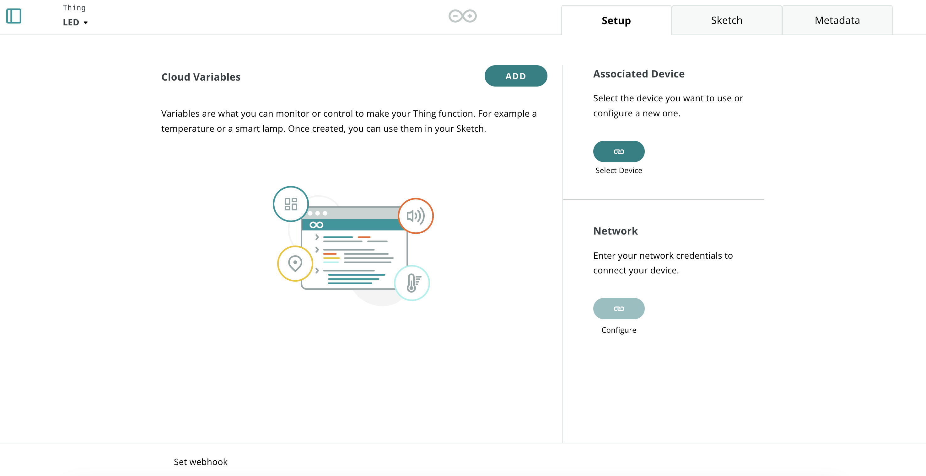
Under associated devices hit select device and then select the Arduino MKR (in our case Janis). And hit associate.

Then below on the dashboard hit configure network, and put in the WiFi SSD and Password we defined above for the MIT network.

Finally, we need to add a new variable that the Arduino can access. This is the variable that gets stored in the online database. I’m going to call it led_command. It’s a boolean value (either true/false). The Arduino can read/write the variable and we update it when it changes. When you’ve set these settings, hit add variable.

Now your final dashboard should look like this:

Programming the Arduino
Now we need to add a little code to control the LED using this variable we just created. This code will use the built in RGB LED on the MKR board.
At the very top, near the imports, include the wifi_drv library. This lets us control the LED.
#include <utility/wifi_drv.h>Then, in the setup() code block, setup the three channels that each control the R, G, and B of the LED. If you want to learn more about what an RGB LED is, look here!
WiFiDrv::pinMode(25, OUTPUT); //define green pin
WiFiDrv::pinMode(26, OUTPUT); //define red pin
WiFiDrv::pinMode(27, OUTPUT); //define blue pin
Now we’re going to write the main code. If the led_command variable is set to True, then we’ll set the LED to Green, whereas if it’s False we’ll set the LED to RED. Note that there are two code blocks at the bottom of the sketch we’ve opened. There’s loop() and there’s onLedCommandChange(), the second is an automated function that runs every time the variable led_command changes, and Arduino set this up for us automatically! In that block we’re going to put the following:
if(led_command)
  {
    WiFiDrv::analogWrite(25, 255);
    WiFiDrv::analogWrite(26, 0);
    WiFiDrv::analogWrite(27, 0);
  }
  else
  {
    WiFiDrv::analogWrite(25, 0);
    WiFiDrv::analogWrite(26, 255);
    WiFiDrv::analogWrite(27, 0);
  }
The final code should look like this:
/*
  Sketch generated by the Arduino IoT Cloud Thing "Untitled"
  https://create.arduino.cc/cloud/things/d40137c5-9c2a-465c-9779-65d8ff950cb2

  Arduino IoT Cloud Variables description

  The following variables are automatically generated and updated when changes are made to the Thing

  bool led_command;

  Variables which are marked as READ/WRITE in the Cloud Thing will also have functions
  which are called when their values are changed from the Dashboard.
  These functions are generated with the Thing and added at the end of this sketch.
*/

#include "thingProperties.h"
// add the import
#include <utility/wifi_drv.h>

void setup() {

  //add the LED pins
  WiFiDrv::pinMode(25, OUTPUT); //define green pin
  WiFiDrv::pinMode(26, OUTPUT); //define red pin
  WiFiDrv::pinMode(27, OUTPUT); //define blue pin

  // Initialize serial and wait for port to open:
  Serial.begin(9600);
  // This delay gives the chance to wait for a Serial Monitor without blocking if none is found
  delay(1500);

  // Defined in thingProperties.h
  initProperties();

  // Connect to Arduino IoT Cloud
  ArduinoCloud.begin(ArduinoIoTPreferredConnection);

  /*
     The following function allows you to obtain more information
     related to the state of network and IoT Cloud connection and errors
     the higher number the more granular information you’ll get.
     The default is 0 (only errors).
     Maximum is 4
 */
  setDebugMessageLevel(2);
  ArduinoCloud.printDebugInfo();
}

void loop() {
  ArduinoCloud.update();
  // Your code here

}


/*
  Since LedCommand is READ_WRITE variable, onLedCommandChange() is
  executed every time a new value is received from IoT Cloud.
*/
void onLedCommandChange()  {
  // Add your code here to act upon LedCommand change
  if(led_command)
  {
    WiFiDrv::analogWrite(25, 255);
    WiFiDrv::analogWrite(26, 0);
    WiFiDrv::analogWrite(27, 0);
  }
  else
  {
    WiFiDrv::analogWrite(25, 0);
    WiFiDrv::analogWrite(26, 255);
    WiFiDrv::analogWrite(27, 0);
  }
}
Now lets hit upload and try it! Nothing will happen right now because we haven’t updated the value of the LED! So we need to do that next.
Creating a Dashboard
Navigate to the Dashboards tab of Arduino Cloud and select create a new Dashboard. Dashboards are how we can control our variables using Graphical User Interfaces (or GUIs), like the ones on our phone.

Now that you’ve created a new dashboard, name it something like LED Control and then select phone view by clicking on the little phone icon. Then hit add > widgets > switch.

Next step, is to configure the switch. Select the three dots next to the switch and hit edit settings. Now the following pane comes up. I named the switch LED Control Switch but you can name it as you please. Then Link the variable led_command and hit done.


Now if you toggle the switch on the dashboard, you should see the LED switch from green to red and back on your Arduino! But there’s one last step, which is connecting this all to the phone.
Shifting the Dashboard to the Phone
Open the phone and open the Arduino IoT Remote app. Go to dashboards, and swipe down to reload the page. You can also close out of the app and re-open it for the same effect. You should now see the dashboard you just created pop up. In our case it is called LED_dash.


Now if you toggle the LED switch the light on the Arduino should change!!! Jump and scream and shout! You did it!

So that was the basic idea of things you can do with Arduino IoT cloud and how to get a phone to share data with an Arduino. This was a very simple example, but you can do much more complicated things! We’ll explore a lot of these things in the next labs.
Graphing Sensor Data to Your Phone
The next thing we’re going to try is graphing sensor data to your phone. Note that we don’t have a sensor to plug into your Arduino right now so we will “spoof” a sensor signal by using a random number generator. First, we need to setup a new variable in the Arduino cloud though. Go back to your LED thing and create a new variable. Set it to a floating point number which updates every 1s. This will setup the code for automated updating! It will “poll” the variable every 1 second.

Note that Arduino has automatically added a function in your sketch called onSensorChange(). The difference is, we don’t need to touch this function this time. This function is used if something else updates the value of the variable and the Arduino needs to do something with it. In this case we’re going to “poll” from the sensor, and have the dashboard update automatically. So we will put this code in the main file.
The following code that increments and decrements the sensor value based on wether the LED is on or off. This doesn’t emulate any realistic sensor, it’s just an example. We also limit the range of the value between -10 and 10 so it doesnt grow too big or small. Note that while this is constantly updating the sensor value, it will only actually update online every 1s.
if (led_command) {
    sensor = sensor + 1.0;
}
else {
    sensor = sensor - 1.0;
}
sensor = constrain(sensor, -10.0, 10.0);
The whole code sketch should now look like this:
/*
  Sketch generated by the Arduino IoT Cloud Thing "Untitled"
  https://create.arduino.cc/cloud/things/d40137c5-9c2a-465c-9779-65d8ff950cb2

  Arduino IoT Cloud Variables description

  The following variables are automatically generated and updated when changes are made to the Thing

  float sensor;
  bool led_command;

  Variables which are marked as READ/WRITE in the Cloud Thing will also have functions
  which are called when their values are changed from the Dashboard.
  These functions are generated with the Thing and added at the end of this sketch.
*/

#include "thingProperties.h"
// add the import
#include <utility/wifi_drv.h>

void setup() {
  //add the LED pins
  WiFiDrv::pinMode(25, OUTPUT); //define green pin
  WiFiDrv::pinMode(26, OUTPUT); //define red pin
  WiFiDrv::pinMode(27, OUTPUT); //define blue pin

  // Initialize serial and wait for port to open:
  Serial.begin(9600);
  // This delay gives the chance to wait for a Serial Monitor without blocking if none is found
  //delay(1500);

  // Defined in thingProperties.h
  initProperties();

  // Connect to Arduino IoT Cloud
  ArduinoCloud.begin(ArduinoIoTPreferredConnection);

  /*
     The following function allows you to obtain more information
     related to the state of network and IoT Cloud connection and errors
     the higher number the more granular information you’ll get.
     The default is 0 (only errors).
     Maximum is 4
 */
  setDebugMessageLevel(2);
  ArduinoCloud.printDebugInfo();
}

void loop() {
  ArduinoCloud.update();
  // Your code here

  // Add your code here to act upon Sensor change
  if (led_command) {
    sensor = sensor + 1.0;
  }
  else {
    sensor = sensor - 1.0;
  }
  sensor = constrain(sensor, -10.0, 10.0);
}


/*
  Since LedCommand is READ_WRITE variable, onLedCommandChange() is
  executed every time a new value is received from IoT Cloud.
*/
void onLedCommandChange()  {
  // Add your code here to act upon LedCommand change
  if(led_command)
  {
    WiFiDrv::analogWrite(25, 255);
    WiFiDrv::analogWrite(26, 0);
    WiFiDrv::analogWrite(27, 0);
  }
  else
  {
    WiFiDrv::analogWrite(25, 0);
    WiFiDrv::analogWrite(26, 255);
    WiFiDrv::analogWrite(27, 0);
  }
}

/*
  Since Sensor is READ_WRITE variable, onSensorChange() is
  executed every time a new value is received from IoT Cloud.
*/
void onSensorChange()  {
// leave this empty
}
Let’s upload and try this! You might be noticing that it takes around 15s for the Arduino to come back online after a sketch upload. That’s because of this line in the code. We can remove it later to make it come online faster.
delay(1500); Note that you should see two things. First, the phone dashboard that lets you toggle the LED on and off should still work. Second we should now see the value of sensor updating on the setup page of the sketch. Nowe we can go to our dashboard and add a chart that updates with the value of sensor.

The dashboard from your phone should also update and you should see the data in realtime as you toggle the LED. Again, note that not every value of the sensor is displayed. It’s only displayed when the sensor is polled every 1 second. Which means we’re missing a lot of the value in the middle because the main loop executes very fast. We’ll learn how to deal with that in later labs.

Congrats!! You’re now graphing variables from a fake sensor to your phone dashboard!!!
Sending Push Notifications to Your Phone
Yes! That’s right. You can send PUSH notifications to your phone from Arduino IoT cloud! So you can maybe troll yourself or your friends. Here we’ll send a notification every time the LED status changes. We’ve linked the original tutorial below for your reference! We won’t be able to do it in this lab because we have to upgrade our Arduino Cloud plan (boo). But it’s good to be aware of capabilities!
Ideas for Next Year
- Pokemon go with the Arduinos (if the GPS location == a known location within a certain radius, you caught a pokemon!)