Reading 1 — Introduction to Electronics (how to not explode everything)
The title of this first reading is Introduction to Electronics: how to not explode everything and that’s exactly what it is. This reading is about the basics of wiring, powering, and connecting electrical devices, and what to consider when trying to do this so that you don’t damage the devices, or yourselves.
This reading includes the following topics:
- The basic definition of a circuit, concepts of power sources, sinks, and flow.
- Basic circuit components.
- Electricity-Water analogy.
- Short Circuits (and the sadness that results).
- Kirchoff’s laws, Ohm’s law.
- Series and Parallel.
- Power, Energy, and Component Ratings.
Basic Circuit Theory and Reminders
This section contains a basic introduction to circuits for those of you who feel you might need a memory jog. There’s no shame! We encourage you to skim this section, and dive deeper into things you feel less comfortable with. We’ve linked a lot of resources, and feel free to ask any questions.
Definition of a Circuit
Ok so what is a Circuit? We have created a three-part definition.
 (from byjus.com)
A Circuit…
is a closed path..
has components that perform functions…
has components that are dependent on each other.
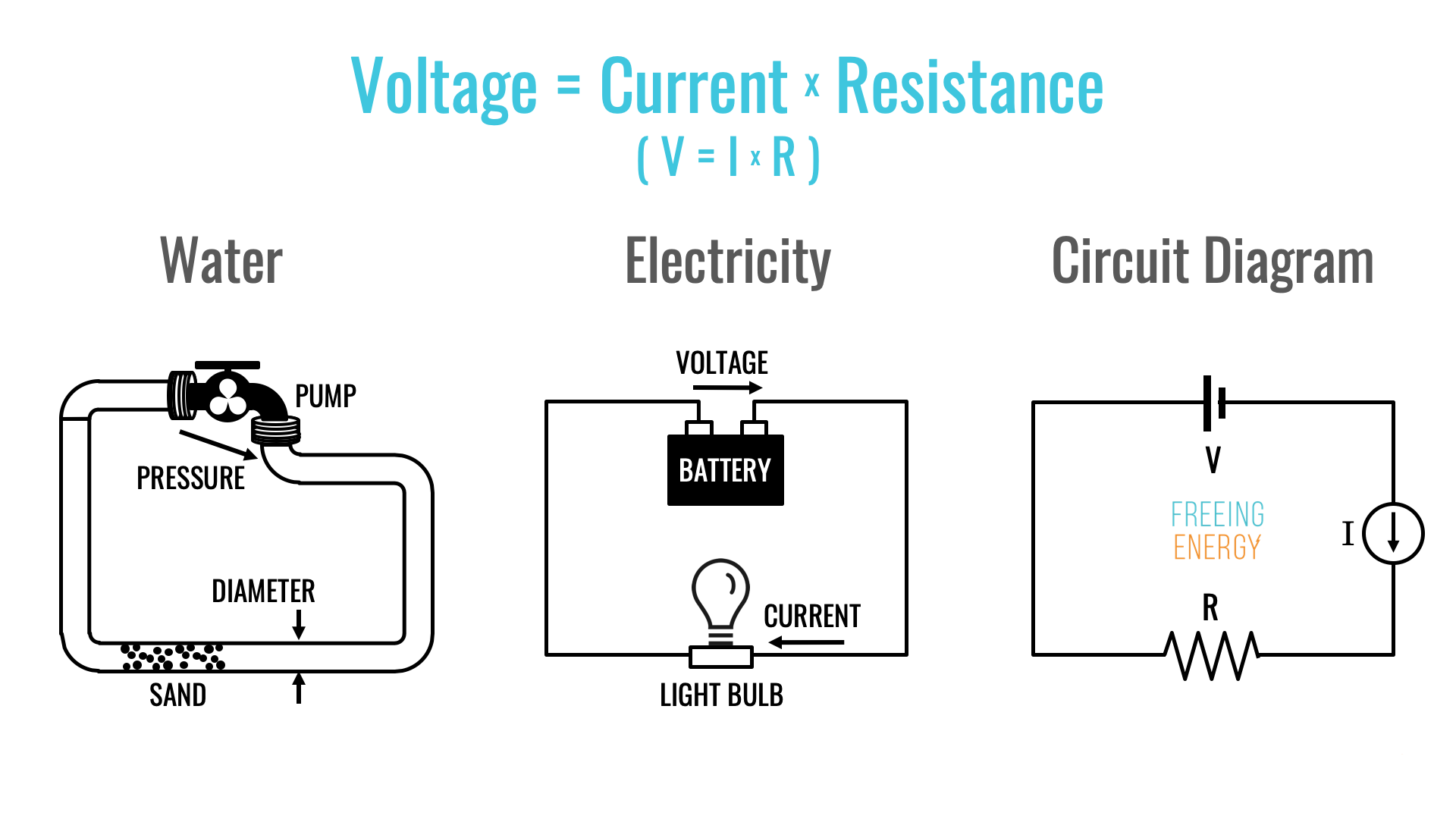
The Classic Electricity-Water Analogy
 (from Freeing Energy ↗)
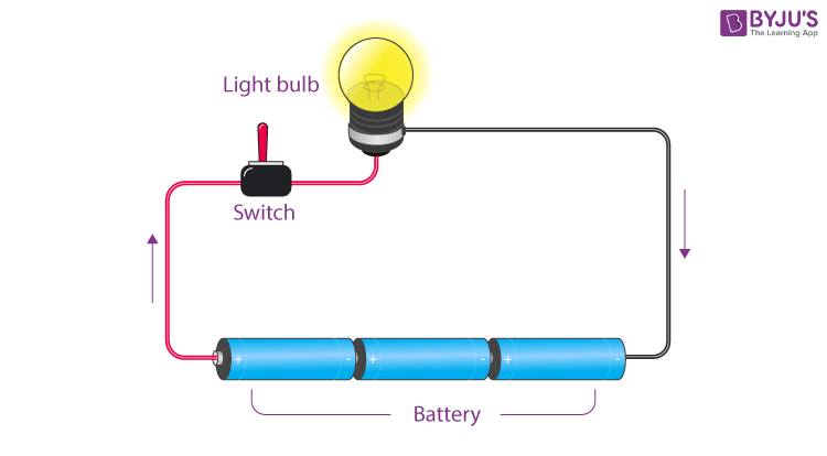
The circuit-water analogy is pretty common and I think a good way to think about how circuits work. Let’s say you have a closed system of water in a pipe and you want to get it to flow. You may add a pump that adds pressure (which is analogus to voltage) to push the water along, and the more you push the faster the water will flow (this is the current). Maybe there’s some debris in the pipe (that’s like electrical resistance) that will kinda push back on the flow of the water slowing it down. If the water doesn’t return back to the bottom side of the pump, unless you have an infinite resevoir of water on the other side of the pump, you’ll just run out of water and no energy will be transferred (this is where the analogy becomes a little fuzzy but you can see how it helps build intuition).

The Law of Conservation of Energy
Everything in the universe follows the Law of Conservation of Energy which states that Energy cannot be created or destroyed, it can only be transferred. In the circuit above, the battery supplies energy to the light-bulb, which emits it as heat and light. The lightbulb is a resistor, and restricts how fast the energy is transferred by slowing down the flow of electrons. The electrons have to push through the dense structure of the light-bulb, and in the process the friction generates heat, and generates light (somewhat, pretend that’s true so we don’t need to study the microscopic structure of materials for now).
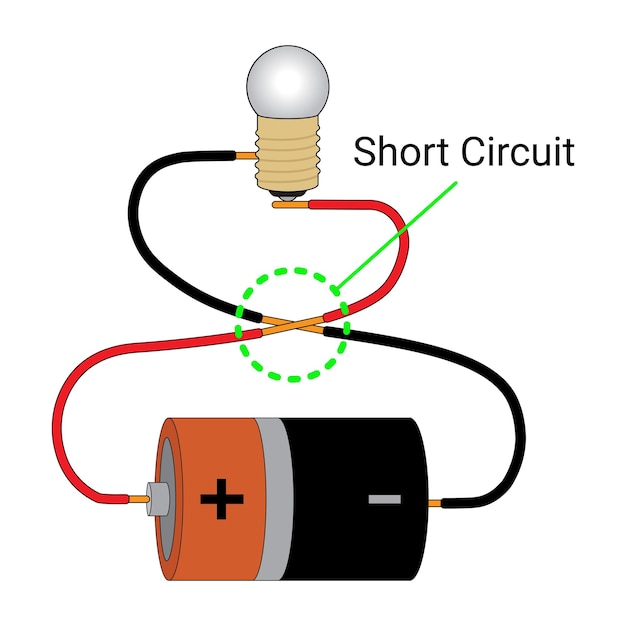
Short Circuits + Fires :)
Let’s say I have an ideal set of wires (so it doesn’t have any resistance) and I have a lightbulb, but I connect it wrong so the wires are accidentally touching, what happens?
 (from freepik.com)
Normally in this circuit, the lightbulb would act as a resistor and limit the current. The energy would be transferred from the battery to the lightbulb, and then the lightbulb would glow. In this case two things are happening. Let’s draw a circuit diagram.
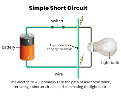 (from ahouseonarock.com)
Let’s say I’m a little electron, and I leave the battery on my adventure around the circut. At some point, I arrive at a junction. I can either go straight and through the path with the lightbulb, or I can take a right turn down the path where the two wires are “bridged.” What do I do?
According to the laws of thermodynamics, I want to be a lazy couch potato. Maximum entropy, minimum effort. If I choose the lightbulb path, I have to deal with the resistance of the lightbulb, and I’ll have to squeeze through some tight spaces and that will slow me down, so I might as well not go there and go through the wire.
But… there’s nothing to limit how fast I can go, and I’m hungry and I want to get back home quickly. So I’m going to move through that wire as fast as I can! Like a Bugatti on the German Autobahn. Max speed.
Bringing this back to circuits, essentially 100% of the energy will be dissipated in this “bridge” connecting the two parts of the circuit, no current will flow in the lightbulb, and the lightbulb will not turn one. But I still might get a light source, how?
Well, I’m still dissipating the same amount of energy, just a whole lot quicker than the physical components of this circuit (the battery and the wire) can actually handle. So I’ll get a light source but not the one I wanted. A fire! Note this concept of the rate of energy dissipation, this is called power (energy/time) and it will become important later.
Circuit Analysis
For the circuit analysis section, I think the videos from Crash Course are really good. Skim them, see if you remember! And if not, go back and watch them so you remember the basics!
Basic Circuit Components
For this section, we’re introducing familiarity with circuit components. You don’t need to know exactly how all these components work, or the physics and equations behind them. But we do want you to be familiar! We can break down components into three categories:
Energy Storage
Energy storage components store energy. These can be sources, like batteries, but they can also be passive components that hold energy for a short period of time that allow us to do other things (like fiter signals, change voltage levels, and more). Here’s a basic list of energy storage components.
| Component | Image | Description |
|---|---|---|
| Battery |  | Batteries store electrical energy. They have a specified voltage, and as energy is used, and charge leaves the positive terminal and returns to the negative terminal, the voltage slowly goes down until the battery is discharged. Charging a rechargeable battery involves moving the charge back from the negative terminal to the positive terminal, but this depends on the battery chemistry. |
| Capacitor |  | Capacitors are reservoirs of charge like batteries. But unlike batteries they aren’t designed for storing it over long periods of time. If you disconnect a capacitor from a circuit, it will generally lose the charge stored in it (except for certain chemistries called super capacitors). Capacitors are used in power electronics to store charge, and in logic electronics to filter signals. But we’ll talk about that later. |
| Inductor | 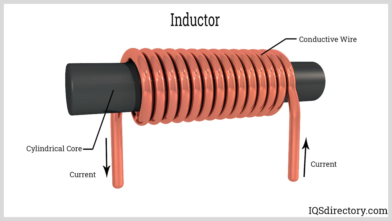 | While batteries and capacitor store energy in the form of charge, inductors store energy in magnetic fields. Inductors resist the change in current of an electric circuit, and can sometimes act as energy use devices if the magnetic energy is used outside the circuit to drive a motor or a magnet. They’re heavily used in filters and power electronics, transformers, and more! |
Energy Use
Energy use components take that energy and use it to do work. That could be mechanical work, outputting light, or anything else that translate the electrical energy into another form of energy. Here’s a list of a few of those components:
| Component | Image | Description |
|---|---|---|
| Resistors | 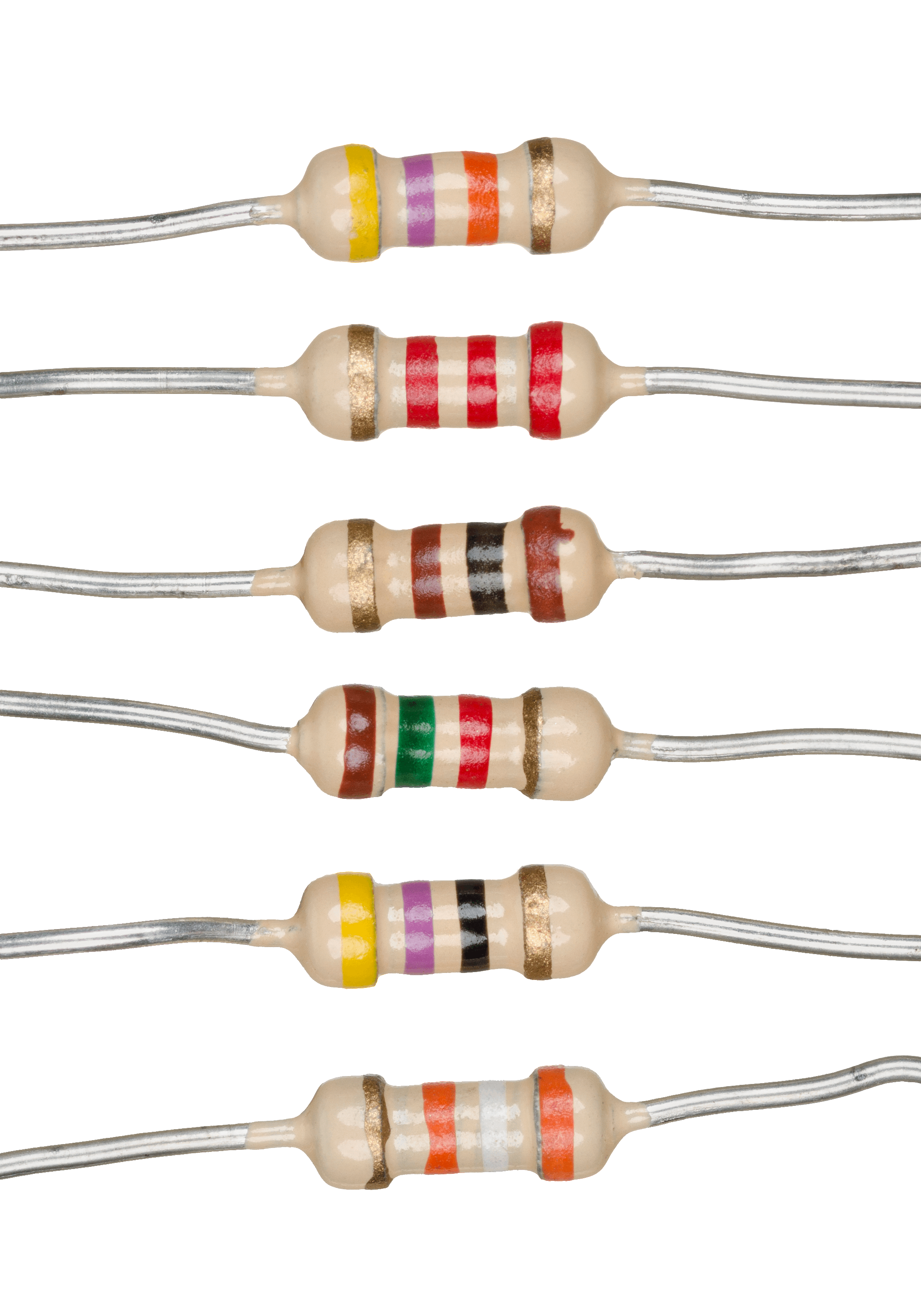 | Resistors we’ve talked about above, but they use their internal structure and material properties to resist the flow of electrical current. Resistors follow Ohm’s Law, V=IR. Energy in resistors is dissipated as heat, and in the case of incandescent lightbulbs, light. |
| Motors |  | A motor is an electro-mechanical transducer. It converts electrical energy into mechanical energy and vice-versa. We will learn more about motors later in this class. |
| Data Processing Chips / ICs | 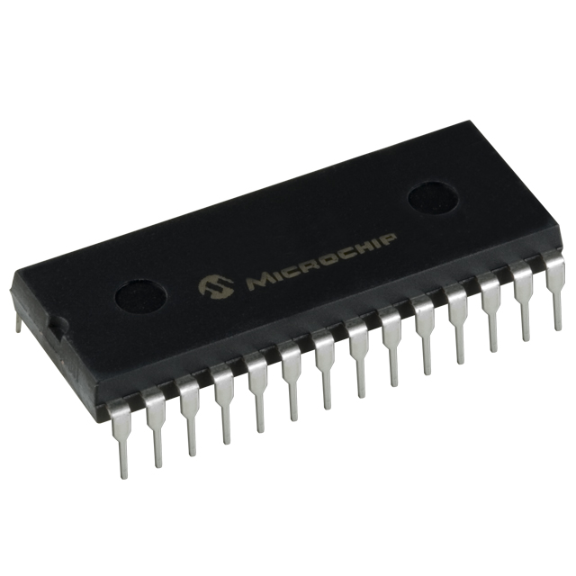 | Integrated Circuits are components that take in data and process them. To do this they require power, all be it a small amount, but still use energy to do things! Your arduino is a good example of this! |
Energy Transfer / Flow Control
| Component | Image | Description |
|---|---|---|
| Diodes |  | Diodes are kind of like one-way valves for current. They only allow current to flow in one direction, and block it from flowing the other way, same with signals. Some special diodes called LEDs (Light Emitting Diodes), will give off light when current is flowing through them. They do this differently than a resistor and more efficiently! |
| Wires | 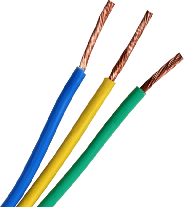 | Wires transfer electrical current. Ideal wires have no resistance but real wires do. The larger the diameter of a wire, the more current it can transfer. If you transfer too much current through a wire, the resistance will be high enough such that the wire will heat up enough such that it will melt! Wire sizing is very important, and we will cover it more below. |
| Switches + Transistors | 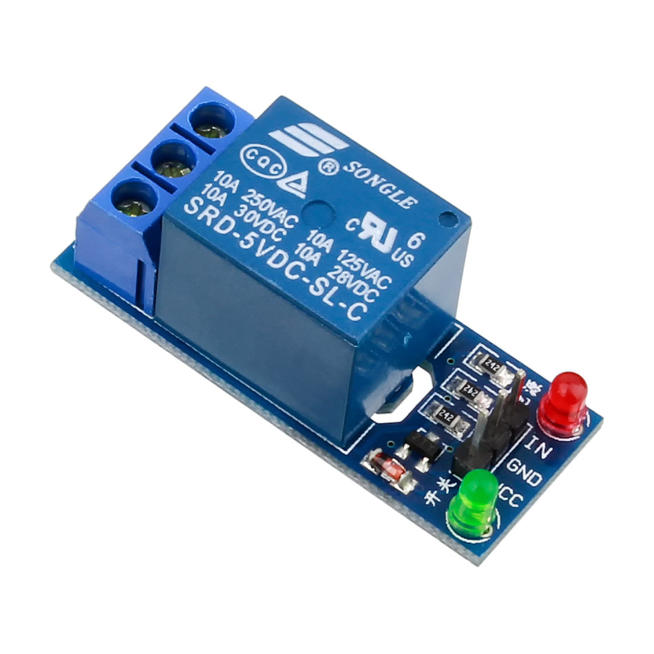 | Switches, like realys and MOSFETs, can switch energy from one part of a circuit to another. They’re critical in many power electronics and drive applications, but we’ll see other examples of them being used in this class! |
And certain components like transformes both store, and transfer energy.
All of the components in the three categories above, generally get translated to circuit symbols so we can draw them easily on schematics. Schematics are “diagrams” of circuits we use to communicate design intent.
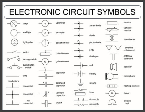
Here are some circuit symbols of components!
Component Ratings, Polarity, and Assembly
This section contains stuff you might be less familiar with. How to pick and assemble parts of a physical circuit in the real world. We’ll do a basic example, but remember that what we’re about to do applies to ALL components you’re going to connect. We’ll do more of this in Lab 0, and future labs too!
The Basics of Component Ratings
Let’s look at a real circuit component, take a look at this resistor on DigiKey ↗. Note that is has a resistance (4.3kOhm) like we would expect. But it also has a power rating (0.25W). Other components, like this capacitor ↗ have a capacity rating (which makes sense), but also a voltage rating. Why?
Well circuits are made of physical components right, and because they operate in the real world, the physical limitations of materials and cooling will limit what we can actually do with them. For example, you can imagine if we try to dissipate 1 Mega-Watt of power (about half of what a wind turbine produces) in a single resistor, it might explode. And you’d be correct! That’s an extreme example, but not considering these limitations of components can cause you problems when building circuits. In general it’s important to look for three main component ratings.
| Rating | Description |
|---|---|
| Voltage | The voltage rating is the highest voltage that can be applied to a component before it fails. For example, if you hook a 16V battery to a 5V capacitor, it would not work anymore. |
| Current | The current rating is the maximum amount of current that can be applied to a component before it fails. For example, if you have a battery that has a volage of 10V has a discharge rating of 1A, and you connect a resistor of 0.5 Ohms to it, that resistor will try to draw 10V/0.5Ohms = 20A of current (because Ohm’s law always applies). The battery will heat up, and likely fail in the form of a fire! |
| Power | Power ratings are typical on resistors, and represent the maximum Voltage X Current that can be passed through a component. For example, a resistor rated to 1W can handle 1V and 1A at the same time. It can also handle 0.5V and 2A, and 2V and 0.5A. But it cannot handle 2V and 2A. |
An Exercise in Component Selection
Let’s say we wanted to assemble a REAL circuit with a battery, and an LED. How would we design this circuit? We have picked the LED for you, and we’ll do math to get the rest of it to work.
Step 1, Pick a Resistor
Brief aside for those who don’t know, anyone who does know can skip this section. LEDs shine with a brightness proportional to the current flowing through them. Most LED circuits have what is called a “current limiting resistor” which limits the current from the power source to an appropriate level for the LED. If the resistor is not there, the LED would burn out immediately when hooked up to a voltage source.
LEDs also have a voltage drop across them when they are turned on. This voltage drop is NOT proportional to the current through the LED nor the applied voltage, however is specific to the LED and is based on the internal characteristics of the silicone. We can draw the following circuit diagram for the LED, resistor, and power connector.
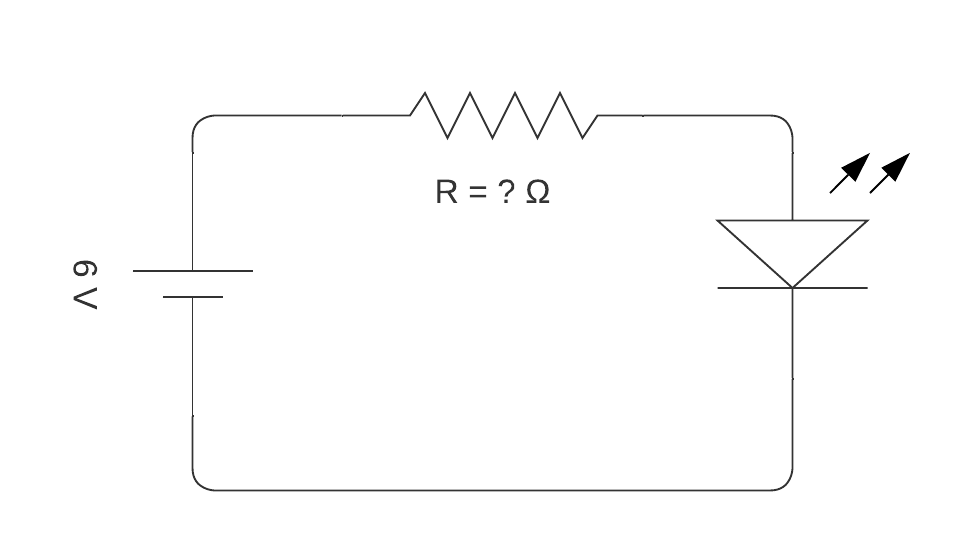
If we look @ the datasheet for a typical LED ↗ we can see the values of the two parameters we care about, the forward voltage, and forward current per chip. In this case, the forward current needed for the LED to work is 20mA. Let’s call this $ I_{fw} $. When on, the LED will have a voltage drop between 1.7-2.6V, let’s call this $V_{drop}$.
Now let’s assume we’ll power the board with four AA batteries (if we’re making a flashlight), that’s a voltage of 6V if they’re in series. Let’s call this voltage $V_{in}$. The current can be calculated as follows. The value of the resistor is $R_{limit}$.
$I_{fw} = \frac{V_{in}-V_{drop}}{R_{limit}}$ (Ohm’s Law)
That means the voltage across the resistor at MAXIMUM will be 6V-1.7V which is 4.3V, so if we want 20mA of forward current, $R_{limit}$ must be 215 Ohms.
Note that we took the lower bound of the typical LED forward voltage range, this is to ensure we don’t accidentally under-size the resistor and send too much current through the LED.
We need to finally, consider this resistor’s power rating. Remember the maximum voltage across the resistor will be 4.3V, and the current will be around 20mA.
$P_{r} = V_{drop}*I_{fw}$
$P_{r} = 4.3 V * 20*10^{-3} A$
$P_{r} \approx 0.086 W$
This resistor ↗ is 215 Ohms and 1/4 Watt. So we could use this!
Step 2, Let’s Pick some Wires
So we want to now pick some wires that we can use to connect the battery to the resistor and the LED. For wires, we can look at the rating tables for various wire sizes. The gauge of the wire is a measurement of the wire’s diameter.
Check out this table on wire ratings based on gauge ↗. Now it has a lot more information than we need. But let’s look at the specs of 32 AWG wire.
Copper Wire Gauge: 32 AWG Cross Sectional Area: 0.0324 mm^2 Max Amps for Chassis Wiring: 0.53 A Max Amps for Power Transmission: 0.091 A
We’re transmitting power! So 0.091 A is > 0.086. Now these number are close, but it means 32 AWG wire is the smallest wire that we would resonably try to use for this application.
Step 3, Let’s Check the Batteries
So above, we assumed we would use (4x) AA batteries in series. At 1.5V each, voltage ADDs in series, but current stays the same. In series, battery capacity and current rating also stays the same because each battery has the same current going through it. In parallel, voltage stays the same, current rating and capacity add.
Batteries in Series and Parallel ↗
That’s a 6V battery. We need to check the current rating now. According to google, a AA battery has a current rating of around 2A, which is much larger than the 0.086A we want to supply. So we’re OK!
But what if I wanted to know how long my system would run for until the battery was dead? Well here we use capacity.
The capacity of a AA battery is 2000 mah (milli-amp-hours), which is 2000 mA X hours. That means if you discharged the battery at 2A=2000mA, it would last for 1 hour until it was fully drained. We are discharging at 0.086A. Note that 2000 mah = 2 Ah (amp-hours).
$ \frac{2 Ah}{0.086 A} = 23.35 h$
This means, (4x) AA batteries in series will run this LED for around 23.35 hours! Then we will have to change the batteries!
Types of Circuits
As we get to building circuits, and more advanced stages. Sometimes it’s important to think about the higher level. All the components and rules we mentioned above (and some more) are the basics that make up all circuits. But there are many types of circuits, and we will see two main ones in this class: power electronics circuits, and logic circuits.
Power Electronics Circuits
Power Electronics circuits are responsible for transferring energy, shifting voltage and current levels, and processing power. For example, a motor controller is a power electronics circuit. Your laptop power adapter is also a power electronics circuit.

Your laptop power adapter takes AC power in from the wall, and converts it to DC power to charge your laptop. It uses diodes, MOSFETs, inductors, capacitors and some basic ICs to do this! The circuit diagram below shows the basic layout of one of these systems. Don’t worry, we don’t expect you to understand all of it. It just give you an idea of how we can take components and use them to convert power!

This is what a DC motor controller looks like:

And this is what it’s basic schematic looks like:
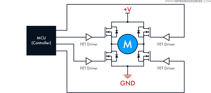
Pretty cool right? We’ll learn more about motor controllers in Lab 3!
Logic Circuits
While power circuits process power, logic circuits process data! These are incredibly complex and are made of many components include ICs, transistors and more! Your arduino is one big logic circuit.

Here is the schematic of an Arduino, and that doesn’t even include what is happening inside the microcontroller (IC) in the middle of the board!

To give you a better example of what some basic logic circuits can do, and breifly how they work. Go onto Lab 0 ! Where we cover some of the basics of Arduino, logic circuits, and programming!